-
-
- Manufacturing
- Industries
- Materials
-
ABOUT
Resources
- Get a Quote
-
My Shapeways
-
0


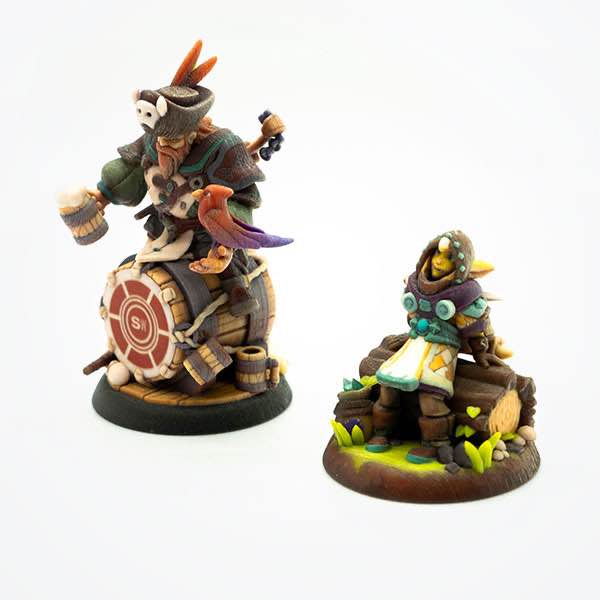
MJP – Visijet is an acrylic material capable of extremely high detail and is a popular choice for hobbyists creating scale models, miniature sets, and other decorative products and is previously known as Fine Detail Plastic. Visijet Tan High Detail is an opaque material that shows exceptional contrast and detail and Visijet Clear Ultra High Detail has an improved clarity, look and resolution.


Maximum Bounding Box
290 x 210 x 145 mm (Tan)
290 x 210 x 100 mm (Clear Ultra)
Minimum Bounding Box
X + Y + Z > 12 mm
The bounding box is a 3D imaginary outline of a box that encloses the smallest area occupied by your model. Your model must be within the minimum and maximum bounding box sizes. If the size of the model is close to the maximum bounding box, then the printing orientation will be restricted.
A supported wall is connected at least on two sides of the wall, while an unsupported wall is connected only on one side of the wall. Walls that do not meet the minimum requirements may not survive printing and cleaning processes. Additionally, models may still be rejected based on the wall geometry of the model. Please consider the size of your model and reinforce the walls or add support structures as needed as minimum guidelines will not always be adequate for large models.
0.8 mm diameter (or thinnest dimension if not circular).
1.0 mm diameter (or thinnest dimension if not circular) for sprues, or wires bearing weight.
1.0 mm diameter (or thinnest dimension if not circular)
A wire is a circular, rectangular or even triangular feature that is thinner in its unconnected directions than its length. A supported wire is connected at least on two sides of the model, while an unsupported wire is connected on one side of the model. Wires that do not meet the minimum requirements may not survive printing and cleaning processes. Additionally, models may still be rejected based on the wire geometry of the model. Please consider the size of your model and reinforce the wires or add support structures as needed as minimum guidelines will not always be adequate for large models.
0.1 mm high & wide
0.1 mm high & wide
For text, the ratio between width and depth, should be 1:1 and sans-serif fonts are preferred for line weight consistency.
One escape hole is not adequate for this material
4.0 mm diameter
Escape holes are necessary to empty the support material of a hollow model. Two escape holes at the opposite ends of the model is optimal for the support removal process. Please consider the size of your model and make the escape holes bigger or add more escape holes as needed as minimum guidelines will not always be adequate for large models.
0.05 mm
Clearance is the space between two individual parts in a model. If the space among the individual parts do not meet the minimum clearance, then parts can fuse together or can be difficult to clean. This is important for movable pieces like hinges, gears, etc.
Interlocking
Yes
Enclosed
No
± 0.3 - 0.7 mm for every 100 mm

"*" indicates required fields
From product development to industrial 3D manufacturing, we can help you scale your business.
contact sales